
Supercapacitors (SC) are described by the same basic equations as conventional capacitors but use electrodes with larger surfaces and a thinner dielectric to achieve far greater capacities. Below is a brief overview of the characteristics of the capacitors to understand and appreciate the ideas behind the SC.
1. CAPACITORS AND SUPERCAPACITORS
A capacitor is a device composed by two nearby conductive surfaces (electrodes) and to which a potential difference is applied and charges are carried on one of the two surfaces, so that charges of opposite sign are generated on the other. The charges are kept separate by a dielectric, thus producing an electric field that allows the capacitor to store energy.
The capacitance C of a conductor is defined as the ratio of the (positive) stored charge Q to the applied voltage V:![]()
For a conventional capacitor, C is directly proportional to the area A of the surface of each electrode and inversely proportional to the distance d between the electrodes:
![]()
where ε0 is the dielectric constant (or permittivity) of the vacuum and εr is the relative dielectric constant of the insulating medium placed between the two electrodes.
The two main properties of a capacitor are its specific energy Esp and its specific power Psp. For both specific quantities they can be calculated as per unit of mass or per unit of volume. The energy E stored in a capacitor is directly proportional to its capacitance and to the square of the applied voltage:
![]()
In general, the power P is the energy delivered per unit of time. To determine P for a capacitor, it is necessary to consider the device as generally forming part of a circuit where an external resistance R is connected in series to it. The internal components of a capacitor (for example the current collectors, electrodes, and dielectric material) also contribute to resistance, which is measured as a whole by a quantity known as Equivalent Series Resistance (ESR). The voltage during discharge is determined by these resistances. When measured in a condition called coupling impedance (R = ESR), the maximum power Pmax of a capacitor is given by

This relationship shows how ESR can limit the Pmax of a capacitor; so we begin to see what changes in the transition to supercapacitors.
SCs follow the same basic principles as conventional capacitors, the difference is that they incorporate electrodes with a very larger surface area A and a much thinner dielectric that decreases the distance d between the electrodes. Consequently, from equations (2) and (3) derives an increase in both capacitance (reaching tens or hundreds of Fg-1) and energy. The SCs are characterized by an irregular geometry of the electrodes; however, as a first approximation, the capacitance depends (even if not linear) on the value of the electrodes area, the dielectric constant and the distance between the charges.
A comparison between the different types of energy storage devices can be shown schematically using the Ragone plot: it reports the specific power Psp as a function of the specific energy Esp. In Figure 1 we see that conventional capacitors have a relatively high power density but a relatively low energy density when compared with electrochemical batteries and fuel cells, while SCs occupy an intermediate region between conventional capacitors and batteries. The largest SCs, currently, can reach capacitance values above 5000 F while the highest energy density achieved is 30 Whkg-1. The typical values of the ESR for the current SCs on the market are between 80 and 20 mΩ for capacities between 650 and 5000 F.
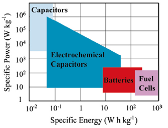
Figure 1: Ragone plot of common energy storage devices
2. SCs TYPE
Electrochemical supercapacitors (also called ultracapacitors) can be divided into electric double-layer capacitors (EDLC), pseudo-capacitors and hybrid type capacitors (Figure 2); they are respectively non-faradic, faradic and a combination of the two (faradic process means a process in which redox reactions take place with transfer of charges between electrodes and electrolyte, as in electrochemical batteries). These types of SC are described below.
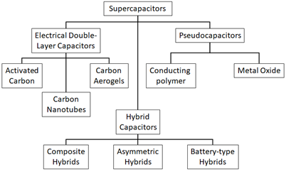
Figure 2: taxonomy of SCs
3. EDLC
The first EDLC was patented in 1957 (a cylinder filled with an electrolyte in which two flat electrodes covered with porous carbon were immersed); the first real EDLC prototype was developed in 1970 in Russia by N. Lidorenko and A. Ivanov. The first marketable EDLC was in 1970 and produced by NEC under the name “supercapacitor” and in general still EDLCs are the main type of SC.
An EDLC is obtained starting from a capacitor by replacing the dielectric with an electrolytic solution and placing on the metal electrodes a layer of porous carbon made conductive (carbon black and active carbon). The surface A to be considered becomes that of the active carbon, made very large thanks to its porosity, and that of the layer of ions adsorbed on it, while the distance d is much smaller because it coincides with the intermolecular distance between the ions of the electrolyte and carbon atoms (Figure 3). Each of the two electrodes therefore acts as one of the two surfaces of two capacitors in series. The two electrodes are separated by a membrane (separator), which allows the mobility of the electrolytic ions and at the same time mechanically prevents a short circuit between the conductive carbon and the metal surface of different electrodes.
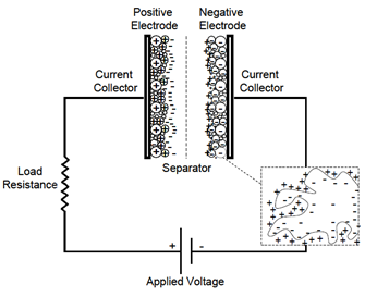
Figure 3: EDLC scheme
As in conventional capacitors, EDLCs store charges electrostatically and there is no charge transfer between electrode and electrolyte (a consequence is that the formation of the bilayer occurs in the order of 10 -8 s). In any case, the electrodes are engineered to prevent recombination of the ions. Since there are no faradic reactions, the accumulation of charges is highly reversible, allowing them a very high cyclic stability: EDLCs can be stable for 106 cycles, while electrochemical batteries are generally limited to about 103 cycles.
The performance and costs of an EDLC depend on those of its components in the proportions shown in Figure 4 (Copyright C 2014 IDTechEx).
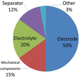
Figure 4: Pie diagram of the percentage of performance and costs of the components of an EDLC.
3.1. ELECTRODES
The electrodes have a layer of porous material that can be made in several ways, in particular we describe various systems with which a carbon and graphene electrode can be made.
Before starting, we note that one might expect that the specific capacity is directly proportional to the surface area of the carbon electrode, but this is not always the case. Often, a type of carbon with a smaller surface area will have a greater specific capacitance than one with a larger surface area. This happens because the actual capacitance of the double-layer varies according to the process used to prepare the carbon. The treatment with which activated carbon is used, for example, affects the porous structure of the electrode surface and the accessibility of its pores to the electrolyte is important. In this regard, we remind you that conductivity is inversely proportional to the size of the particles, so that a material with a larger surface area and which is therefore made of smaller particles have an increased resistance (we will do more in detail later).
Activated Carbon
Activated Carbon (AC) derives from an organic precursor rich in carbon through a carbonization (heat treatment) in an inert atmosphere and then from an activation process that creates the porous network in the volume of the carbon material (Figure 5). This activation is achieved by a partial and controlled oxidation of the precursor of AC.

Figure 5: SEM image of AC particle.
Activated carbon based SCs are the most developed technology due to their low cost, large capacitance, and long cyclic stability. Regarding the low cost, the AC can be produced by carbonization of walnut shells, peat, wood, lignite, and coal.
Activated carbons have a complex porous structure composed of pores of different sizes called micropores (diameter <20 Å), mesopores (diameter 20 – 50 Å) and macropores (diameter> 50 Å). Not all large area surfaces (made of micropores) contribute to the capacity of the device because the solvated ions of an electrolyte, often too large, have difficulty in entering the smallest pores. Conversely, larger pores do not always imply greater capacities, in fact the best performance is obtained with pore sizes similar to that of the solvated ions of the electrolyte used, so that in order to enter the pores they have to deform and ultimately resize the solvation shell that is shape around them, so the charge at the electrodes will be greater (Figure 6).

Figure 6: Scheme of the adsorption of ions in micropores (a), mesopores (b) and macropores (c) of carbon for an electrolytic solution.
Computational simulations (Hartree-Fock method and with the Density Functional Theory) offer an even more detailed explanation of why the capacitance of a carbon electrode is maximum with pores having a size slightly smaller than that of ions: the surface charge density that is generates when the ions come into contact with the electrode implies a potential that causes an elongation of the covalent bonds CC, allowing a more intense packing of the ions in the porous structure; it is like saying that the capacity is then determined not only by the geometry of the pores but also by the entry into themselves of the ions. Usually is possible to correlate the larger pores with a higher specific power and the narrower pores with a higher specific energy. Constructively, to obviate the considerable contact resistance between the collector and the carbon dust grains and between the grains themselves, the active material is generally pressed and stabilized with a polymeric binder on an aluminum sheet which acts simultaneously as an electrical collector and as a mechanical support for carbon powder (Figure 7).
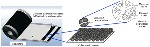
Figure 7: Construction structure of a typical EDLC supercapacitor.
The same type of carbon can be added differently to the two electrodes, creating the so-called Asymmetric EDLC (AEDLC). These devices are generally able to reach higher operating voltages since they exploit the entire electrochemical stability window (ESW) of the electrolytic solution used. In fact, the electrolytic solution can have asymmetrical breakdown voltages (generally the breakdown voltage towards negative potentials is greater than that towards positive potentials, e.g. -1.7V and + 1.3V).
With symmetrical EDLCs (the two electrodes have the same carbon load and approximately the same specific capacitance) the voltage is applied symmetrically to the electrodes and the limit will be defined by double the lowest breakdown voltage in modulus; for example for -1.7V and + 1.3V breakdown voltages, the operating voltage in symmetrical EDLCs can reach 2.6V. In an AEDLC, by varying the ratio of the masses of the active material to the two electrodes, it is possible to fully exploit the asymmetrical potentials, reaching an operating voltage of 3.0V in the previous example (Figure 8).
The ratio between the masses to be used as a function of the electrode characteristics (positive specific capacitance C+ and negative C–) and of the electrolytic solution (positive breakdown voltage ΔV+ and negative ΔV–) can be defined by the following equation:
![]()
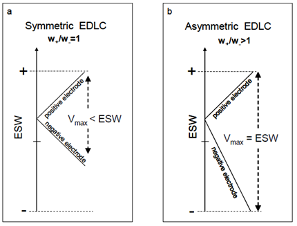
Figure 8: Potential excursion diagram in the symmetrical (a) and asymmetrical (b) configuration.
Carbon aerogel
Carbon aerogels consist of a continuous network of conductive carbon nanoparticles interspersed with mesopores in a gel. Due to this continuous structure and their ability to chemically bond with current collectors, aerogels do not require the application of additional adhesive bonding agents. As electrodes without binders, aerogels have been shown to have a lower ESR than activated carbon, they also have a large area and good conductivity.
The particle size is controlled by the preparation process and in particular smaller particles imply a larger area accessible to the pores.
Carbon nanotube (CN)
Carbon nanotubes (CNs) are carbon filaments, both single-layer and multi-layer, with a diameter ranging from 1 to 50 nm. Electrodes made of this material are fabricated as a nanotube mat with an open and accessible mesopore network: this unique structure is represented in Figure 9.

Figure 9: A “mat” of carbon nanotubes, about 300 m long, vertically aligned on a metal substrate.
Unlike the other carbon-based electrodes, the mesopores of the nanotube electrodes are interconnected, allowing a continuous charge distribution that exploits almost the entire available surface area (Figure 10), even if the nanotubes have a modest area when compared with that of activated carbon. Since the electrolyte ions can diffuse more easily in the mesopore network, carbon nanotube electrodes also have a lower ESR than that of activated carbon. The efficiency of the woven mat structure therefore allows specific energies comparable with other carbon-based materials and the reduced ESR allows greater specific powers.

Figure 10: Diagram of a carbon nanotube electrode.
Diagram of a carbon nanotube electrode.
Graphene
Graphene is a two-dimensional material having carbon atoms arranged in a honeycomb (Figure 11) whose plane can be as thick as a single atom, that is literally a monolayer.
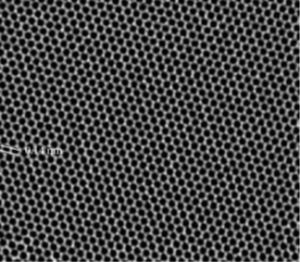
Figure 11: Honeycomb reticular structure of graphene visible thanks to a SEM.
The graphene is obtainable by exfoliation of the graphite and then depositing the individual layers on a substrate. It was synthesized for the first time in 2004 by the research group of prof. Geim and has many properties that make it a unique material under various aspects: it has Young’s modulus (for forces parallel to the plane) equal to that of diamond; has a higher conductivity than silver and copper; it has electron mobility at room temperature much greater than that of in silicon and other semiconductors; it is transparent and flexible, can be manufactured with few defects and impurities. Another outstanding feature of graphene is its particularly large specific surface area, up to 2675 m2g-1. The combination of these properties makes it a material of choice also to produce SC.
3.2 ELECYTOLYTES
Electrolytes represent 20% of the performance and costs of an EDLC (Figure 4) according to the following reasons: the voltage applicable to an electrolytic cell of an SC, and therefore with it the possible energy density, will depend on the breakdown voltage of the electrolyte; the power density instead, depending on the ESR of the cell, will be strongly dependent on the conductivity of the electrolyte.
Electrolytes can be aqueous or organic: the former are aqueous solutions having an acid (such as H2SO4), an alkali metal hydroxide (such as KOH) or a neutral salt (such as KCl) as their electrolyte; the latter are generally made up of quaternary ammonium salts (such as tetraethylammonium tetra fluoroborate or TEATFB) dissolved in aprotic polar organic solvents such as acetonitrile (ACN) and propylene carbonate (PC). Organic electrolytes are most used in commercial devices due to their high breakdown voltage, usually in the range of 2.5-2.7 V. Aqueous electrolytes, on the other hand, have a lower breakdown voltage, typically 1 V, but have a lower breakdown voltage. conductivity better than that of organic.
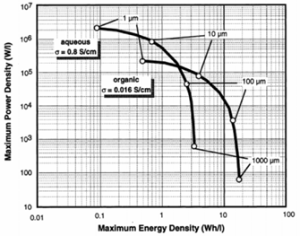
Figure 12: Comparison of Ragone plot for SC using aqueous and organic electrolytes
It is possible to note that aqueous solutions reach higher specific powers but at the same power they give lower energies, this is mainly since the maximum applicable voltage is limited to avoid faradic reactions according to (water electrolysis:
![]()
Cathodic reduction:
![]()
Anodic oxidation:
![]()
Organic electrolytes, on the other hand, can withstand operating voltages up to 2.7 – 2.8V. In the comparison between aqueous and organic electrolytes, however, the reduction in power of the latter with respect to the former (due to the higher ESR) is minimal and acceptable, given the gains in terms of accumulated energy. Furthermore, the fact of using an organic solvent allows the device to work up to about -40°C, while with aqueous electrolytic solutions the limit does not go much below 0°C.
Therefore, as regards commercial products, the use of organic solvents is preferred and two of these, acetonitrile and propylene carbonate, are considered the best. Both have a voltage limit of 2.8V, but the former allows the SC to operate at lower temperatures and, more generally, with lower internal resistances. As for the maximum temperature at which an electrolytic solution can work, the characteristic temperatures of the solvents (boiling, melting, and fl ash point) play a crucial role in the range of temperatures at which they can operate, the safety of the SC largely depends on the flash point (the minimum temperature at which a volatile material can vaporize to form a flammable mixture in the air). In the case of acetonitrile, the temperature range goes from -30°C to 80°C. Currently, TEATFB in acetonitrile is indicated as the best organic electrolyte solution for use in SC, reaching conductivity values up to 60 mScm-1.
3.3 ELECTRICAL DOUBLE LAYER MODELS
The term “double layer” was first used by Helmholtz in 1853, when he envisaged two layers of charge at the interface between two different metals. Later, He compared the metal / metal interface with that metal / aqueous solution. In his model, the interface consists of a layer of electrons on the surface of the electrode and a layer of ions in the electrolyte. In surface science it is often used to work in terms of di ff erential capacity, defined as:
![]()
where σ is the charge density and V is the electric potential.
In the early 1900s, Gouy observed that the capacitance was not a constant but depended on the applied potential and ionic concentration. Gouy then proposed that thermal agitation kept the ions from accumulating on the surface of the electrode, on the contrary forming a charge diffuses in space. Gouy’s theory is resolved in the following differential capacity:
![]()
where z is the valence of the ions and k is the reciprocal of the Debye-Hückel length defined by the equation:
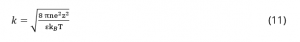
where n is the number of ions per cubic centimeter, T is the absolute temperature and kB is the Boltzmann constant. The capacitance CG resulting from the charge distribution is therefore no longer a constant. This model today is called Gouy and Chapman’s because it was also developed by D.C. Chapman. In 1924, Stern modified the Gouy-Chapman model to include a compact layer as well as the Gouy diffusive layer. The compact Stern layer consists of a layer that is specifically adsorbed by ions. The Stern layer was then divided by Grahame into two regions. He denoted the part of the ions closest to diffusive as the outer Helmholtz plane (this is sometimes called the Gouy plane); the layer of ions adsorbed on the electrode surface was designated as the internal Helmholtz plane (Figure 13).
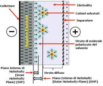
Figure 13: Simplified diagram of a double layer of negative ions on the electrode
Room Temperature Ionic Liquid
An alternative to electrolytic solutions is represented by ionic liquids (Room Temperature Ionic Liquid – RTIL or IL), they are salts which, due to an unfavorable crystalline packing (when for example the cations are particularly large compared to the anions and have a low degree of symmetry), are often liquid at room temperature and at lower temperatures. The ionic nature of these materials and the weak coordination between the ions prevents their evaporation, so the ILs do not have a measurable vapor pressure and have a high chemical stability at high temperatures (even> 400°C). The way in which the bilayer is formed with ionic liquids is different from EDLC due to the absence of a solvent, so the Helmoltz model is no longer valid as can be understood by observing Figure 14.
liquids. Furthermore, the maximum applicable voltage depends very much on humidity: even a few ppm of water can reduce the limit voltage.
3.4 OTHER COMPONENTS
Although they determine the characteristics of a SC in a smaller percentage (Figure 4), the other components, in addition to the electrodes and the electrolyte, also play an important role. All the elements necessary for assembly (the separator, the outlet and the containment system) in addition to affecting the specific power and specific energy, can make the device more e ffi cient through their intelligent engineering.
In the case of aluminum sheets, they are necessary as a mechanical support for an electrode because, whatever the nature of the active materials, they are very often in the form of powder. An aluminum sheet also has the function of a current collector because the conductivity of the carbon is such that it cannot be used except for electrodes with thicknesses not exceeding a few tens of microns.
To stabilize the carbonaceous powders, polymer-based binders are used, which help to form a compact and stable mass and increase the adhesion of the powders to the metal collector. These are generally inert polymers, such as carboxymethylcellulose or polyvinyl fluoride, and ultra-high molecular weight polyethylene, but above all polytetrafluoroethylene. However, they must be used in moderation. If in excessive quantities, they would in fact result in an increase in electrical resistance (they are insulators) and a consequent decrease in specific energy, representing a dead weight for energy storage purposes.
The separator we have already talked about at the beginning of the paragraph on EDLC, must be, as anticipated, chemically inert, so that it cannot degrade over time, and that is why, in the case of organic electrolytes, extensive use is made of cellulose or polypropylene fabrics, while glass fibers are often used in the case of aqueous electrolytes.
The current collectors also affect the specific power through their series resistance, so their role can be optimized by reducing aluminum and improving its geometry. For example, polishing the current collectors, chemically binding the electrode to them, and using thin colloidal films reduce ESR.
4 PSEUDO-CAPACITORS
In pseudo-capacitors, electric charges are mainly accumulated as result of reversible redox reactions (faradic pseudo-capacitance). Its known that oxides and sulphides of transition metals such as RuO2, IrO2, TiS2, or their combinations, take part to many reactions. These reactions are accompanied by electro-adsorption and intercalation processes: let’s see in detail the first two processes mentioned.
Redox reactions
Let us briefly recall what a redox reaction consists. In a reaction of this type an oxidant and a reducing agent are involved. The potential E is given by the Nernst equation (14):
![]()
where E0 is the standard reduction potential, R is the universal gas constant, T is the absolute temperature, n is the number of electrons transferred, F is the Faraday constant, and Q is the reaction quotient.
Ion adsorption
The accumulation of ions to form a single layer on the electrode substrate is a reversible process that results in a faradic charge transfer and therefore involves a pseudo-capacity similar to how explained in the redox reactions.
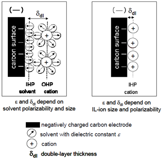
In Figure 15 you can see a comparison between the operating mechanisms of an EDLC and a pseudo-capacitor, in particular we note the different charge separation.
FigurE 15: Scheme of the mechanisms of charge conservation in an (A) EDLC and in a (B) pseudo-capacitor
The specific energy of the pseudo-capacitors is greater than that of the EDLCs, between 10 and 50 Wh/L, as well as their capacity (300-1000 F/g), while their duration reaches hundreds of thousands of cycles (which however, it is less than that of EDLC). As we said earlier, when a potential difference is applied at the extremes of a pseudo-capacitor several processes take place; using the example of a sulfuric acid we have: the loading of the double layers, the redox reactions of different groups on the surface, chemical absorption of hydrogen and the intercalation of hydrogen. Each of these processes can be represented by a step of a model with which the pseudo-capacitor is described through an equivalent electrical circuit of the type in Figure 16.
Even the pseudo-capacitors can be made with several types of electrodes, in particular with conductive polymers or with metal oxides.
Figure 16: Equivalent circuit of a pseudo-capacitor
4.1 ELECTRODES
Conducting polymer
One of the important milestones of modern electrochemistry is the development of conductive polymers. We know that polymers are insulators, but electrochemical reactions can be made to occur in double bond systems, such as polyaniline, polythiophene and polyacetylene, which are reversible and can be used in SCs. It is possible to make a polymer conductive thanks to processes called electrochemical doping of polymers via anions or cations (in analogy with semiconductors).
Conductive polymers have relatively high capacitance and conductivity, along with relatively low ESR and cost comparable to carbon-based materials. Their downside is that they have limitations in stability after many charge and discharge cycles; these limits are explained by the mechanical stress on conducting polymers during the reduction-oxidation reactions.
Metal oxides
Due to their high conductivity, metal oxides have been investigated as possible materials for the electrodes of the pseudo-capacitors. The majority of relevant research concerns ruthenium oxide (RuO2), this is because with other metal oxides the is still low for industrial applications. The capacity of ruthenium oxide (1358 Fg-1) and its good electrical conductivity (3∙102Scm-1) are obtained through the insertion and removal or intercalation of protons in its amorphous structure, according to the following reaction:
![]()
where 0 ≤ x ≤ 2. In its hydrated form (RuO2 ∙ xH2O), the capacitance (720 Fg-1) exceeds that of carbon-based materials and conductive polymers. Furthermore, the ESR of hydrated ruthenium oxide is lower than that of other electrode materials. If a tubular arrangement of porous RuO2∙xH2O structures is used, an even higher specific capacity is obtained (1300 Fg-1).
Unfortunately, the success of ruthenium oxide has been limited by its prohibitive costs. A cheaper alternative can be represented by manganese oxide (MnO2). It has theoretical specific capacitance of 1370 Fg-1, low cost and good environmental compatibility. The charge conservation mechanism for pseudo-capacitors with MnO2 is based on the adsorption on the surface of cations (for example K +, Na + or Li +, indicated in general with C +) as well as the incorporation of protons according to the following reaction:
![]()
In any case, the theoretical capacity is rarely reached in experiments, mainly due to the low electrical conductivity of manganese oxide (≈10-6 Scm-1) which limits the working speed for high power performance and thus hinders its applications in energy storage systems.
Electrodes with metal oxides can only be used with aqueous electrolytes, thereby limiting the voltage applicable to the cell. The gains in power density from the lower resistance are often offset by losses due to the lower working voltage. To summarize the discussion on electrodes, Figure 17 shows the specific capacities of various materials for both EDLCs and pseudo-capacitors.
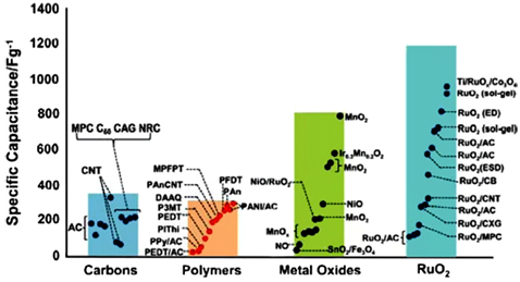
Figure 17: Capacitance performance for both carbon electrode EDLC and pseudo-capacitor electrodes (including transition metal oxides and conducting polymers) Copyright 2008, The Electrochemical Society
5 HYBRYD
In recent years, a new type of SC has appeared, the hybrid system, where carbon and faradic electrodes are combined to increase specific energy. Hybrid electrodes should not be confused with composite electrodes in which one type of material is incorporated into another at the same electrode.
A reason for the transition to a hybrid SC was presented by a published research on conducting polymers at the University of Bologna, according to which a high concentration of polymer cannot be achieved at the negative electrode, but a positive electrode can be built effectively on the polymer and then make the negative one with activated carbon. The results of this research are summarized in the Ragone plot of Figure 18: the triangles represent the hybrid capacitor while the circles the carbon one and the numerical values represent the current density in mAcm-2 (note the improvements in energy density of the passage hybrid).

Figure 18: Ragone plot of a hybrid (N) and a carbon supercapacitor
An advantage of hybrid SCs compared to symmetrical SCs is their high EMAX (because in addition to the higher operating voltage there is a doubling of the capacitance, as only one electrode contributes to it and not two in series as in common EDLC cells) and correspondingly their higher energy specific (up to 10-20 Whkg-1, higher than that of EDLC); also the specific power is greater than that of the EDLC, even if the problem of limited cycling remains due to the faradic component. An advantage over batteries, however, is the possibility of quick charging and easier hermetic sealing. Currently hybrid capacitors of the PbO2/H2SO4/AC type are used in electric wheelchairs and electric motor buses.
5.1 ELECTRODES
Based on the configuration of the electrodes, hybrid SCs are divided into composite, asymmetrical and battery-type.
Composite
Composite electrodes integrate carbon-based materials with conductive polymers or metal oxides and incorporate both physical and chemical charge storage mechanisms in a single electrode. A particular case are the hybrid nanostructured materials: for example, carbon nanotubes integrated with conducting polymers are used, the structural integrity of the intertwining of nanotubes shows to limit the mechanical stress caused by the insertion and removal of ions in the conducting polymers. Therefore, unlike the latter, composite electrodes are able to achieve cyclic stability comparable to that of EDLCs.
It is also possible to obtain ternary hybrid structures formed simultaneously of conducting carbon (for example carbon nanotubes), pseudo-capacitive metal oxides and conducting polymers. Figure 19 shows a scheme of ternary material consisting of a skeleton of carbon nanotubes, covered with manganese oxide and then with a conducting polymer, the PEDOT-PSS.

Figure 19: Ternary structure MnO2/CNTs/PEDOT-PSS (Copyright 2010, American Chemical Society).
The key advantages of nanostructured materials therefore include short electron and ion transport paths, large surfaces area between the electrode and the electrolyte and new reactions not possible in the bulk material (in short, the specific capacity of hybrids has been found to be greater than the sum of those of the individual components). The main disadvantages include the increase of unwanted reactions at the electrode / electrolyte interface, precisely because of the larger area, and potentially more complex syntheses and having higher manufacturing costs.
Asymmetric
Asymmetric hybrid SCs combine faradic and non-faradic processes by coupling an EDLC electrode with a pseudo-capacitor electrode. These capacitors mitigate the contrast between achieving higher energy and power density than EDLCs and have better cyclic stability than pseudo-capacitors.
Battery-like
Like asymmetric hybrids, battery-type hybrids couple two different electrodes, but the latter couple an electrode of a SC with that of a battery. Research has mainly focused on using nickel hydroxide, lead dioxide and LTO (Li4Ti5O12) for one electrode and activated carbon for the other.
Contrary to promising results, the general opinion is that more research will be needed to determine the full potential of battery-type hybrids.